Maintenance-Free Indoor SF6 Load Break Switch-40.5kV
| Brand | ROCKWILL |
| Model NO. | Maintenance-Free Indoor SF6 Load Break Switch-40.5kV |
| Rated voltage | 40.5kV |
| Rated frequency | 50/60Hz |
| Series | FL(R)N36 |
General Information
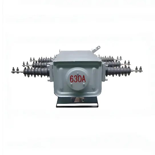
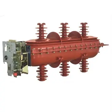
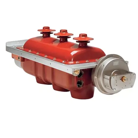
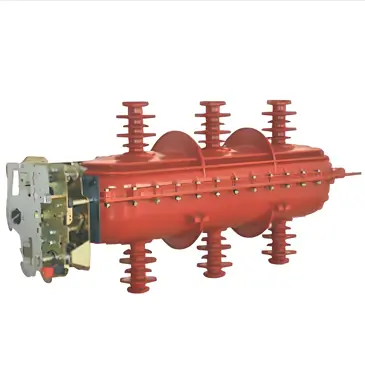
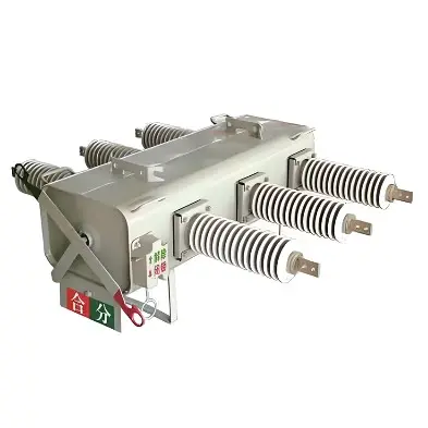
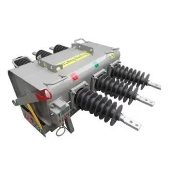
40.5kV Indoor SF6 Switch-Disconnector FL(R)N36 Load Break Switch LBS is a double-break rotary load switch using SF6 gas as the insulating and arc-extinguishing medium. It is suitable for 35-40.5kV power distribution systems. Each switch is permanently sealed after being filled with 0.4bar pressure SF6 gas. The switch can be installed vertically or horizontally. The typical installation method in the ring main unit is to install a steel partition horizontally between the cable room and the busbar room. This installation method isolates the busbar from the cable joint to comply with safety requirements for operation and maintenance.
Combining the FL(R)N36-40.5kV indoor high-voltage SF6 load switch with other electrical components can realize control and protection functions and serve as the control and protection of electrical equipment in industrial and mining enterprises, civil power supply and secondary substations. It is used to make and break load current and overload current. It can also be used to make and break no-load long lines, no-load transformers and capacitor banks. The series combination of load switch and current-limiting fuse can be used instead of a circuit breaker, that is, the load switch is responsible for closing and breaking various load currents, while the current-limiting fuse is responsible for breaking larger overload currents and short-circuit currents.
The product complies with GB3804, GB16926, IEC 60265-1 and GB16926, IEC60420 standards.
Structural Features
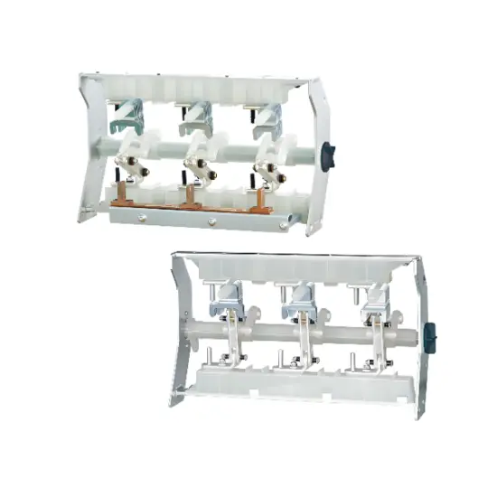
The load switch adopts double-break, rotary movable contacts and has the following three states: closing; opening; grounding.
Good insulation performance. The load switch uses SF6 as arc extinguishing and insulating medium. The switch is sealed by an upper and lower shell cast by epoxy resin.
Good safety performance. If arcing occurs internally, there is a structural weak point at the rear of the enclosure that will burst open, and then the arc vent valve on the cabinet will open and direct the overpressure airflow to the outside of the cabinet.
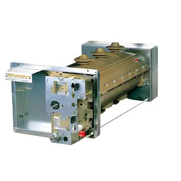
It can be operated manually or electrically, and the operation is convenient and reliable.
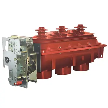
Three-phase integral installation, good periodicity, small number of parts, easy adjustment and installation, simple and easy, and long life.
Each load switch is sealed and maintenance-free for life.
The load switch and operating mechanism are placed in the detachable upper unit. It is easy to change the load switch cabinet into a load switch + fuse combination electrical cabinet, or change the load switch + fuse combination electrical cabinet into a load switch cabinet. .
It can be used as a compact, miniaturized, frequent operation and other places.
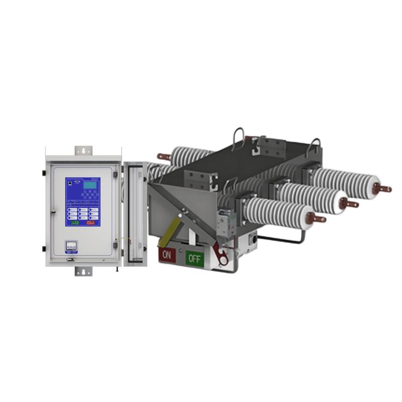
Operating Mechanism
The spring operating mechanism of the load switch and its combined electrical appliances is divided into single spring operating mechanism and double spring operating mechanism. The FLN36-12D load switch equipped with a single spring operating mechanism is mainly used for the incoming and outgoing line control unit. The FLRN36-12D load switch-fuse combination appliance equipped with a double spring operating mechanism is mainly used for transformer protection units.
Usage Environment
- Ambient air temperature: upper limit +40℃, lower limit -15℃.
- Environmental humidity: The daily average relative humidity is not greater than 95%, and the monthly average relative humidity is not greater than 90%.
- Altitude: The maximum altitude of the equipment installation site is 2000m.
- Earthquake: The earthquake intensity does not exceed 8 degrees.
- There is no serious pollution in the surrounding air, such as dust, smoke, chemical corrosives, flammable gases, gasoline and salt agents, etc.
- If you have special requirements, please indicate them when ordering.
Main Parameters
| No. | Items | Unit | Value | |||
| FLN36-40.5 | FLRN36-40.5 | |||||
| 1 | Rated voltage | kV | 40.5 | |||
| 2 | Rated frequency | Hz | 50/60 | |||
| 3 | Rated current | A | 630 | 1250 | ||
| 4 | Rated insulation level | 1 min power frequency withstand voltage | phase to phase | 85 | ||
| phase to earth | kV |
85
|
||||
| fracture |
110
|
|||||
| Lightning impulse withstand voltage(peak) | phase-to-phase |
85
|
||||
| phase to earth | 185 | |||||
| fracture |
215
|
|||||
| 5 | Auxiliary circuit 1 min power frequency | V |
2000
|
|||
| 6 | Rated thermal stability current/duration (3s/2s) | main switch | kA | 20/3 | ||
| earthing switch |
20/2
|
|||||
| 7 | Rated short-circuit making current | kA |
50
|
125
|
||
| 8 | Rated closed circuit breaking current | A |
630
|
|||
| 9 | Rated active load breaking current | A |
630
|
|||
| 10 | Rated cable charging breaking current | A |
10
|
|||
| 11 | Rated transfer current | A |
1700
|
|||
| 12 | Expected short-circuit breaking current | kA |
|
50
|
||
| 13 | Mechanical life | times |
2000
|
|||
| 14 | SF6 gas rated inflation pressure(20℃ gauge pressure) | MPa |
0.06
|
|||
| 15 | SF6 gas highest pressure (20℃ gauge pressure) | MPa |
0.07
|
|||
| 16 | Annual air leakage rate | %/Y |
0.5
|
|||
| 17 | Synchronicity of opening and closing | μs |
≤3
|
|||
| 18 | circuit resistance | mΩ |
≤100
|
|||
Fuse Rated Parameters
| No. | Rated Voltage (KV) | Fuse Rated Current (A) | Fuse Link Rated Current(A) | Rated Breaking Current (KA) |
| 1 | 40.5 | 40 | 6.3,10,16,20,25,31.5,40 | 40 |
| 2 | 40.5 | 100 | 50,63,80,100 | 40 |
| 3 | 40.5 | 125 | 125 | 50 |
Related Products
-
Outdoor RPS-15kV/1250A SF6 load break switch
-
363kV 380kV 400kV 550kV HV SF6 Circuit Breaker supplier
-
24KV Indoor SF6 Load Break Switch
-
SC6-24KV SF6 load break switch
-
12KV SF6 load break switch
-
36KV SF6 Load Break Switch
-
High-performance 11 kV SF6 Load Break Switch
-
Wear-Resistant 15kV SF6 Load Break Switch
-
Medium-voltage Indoor SF6 Load break Switch for power systems 12kV
-
Outdoor Pole-Mounted SF6 Load Switch 12kV