Maintenance-Free Outdoor Metering Unit-11kV、33kV
| Varumärke | ROCKWILL |
| Modellnummer | Maintenance-Free Outdoor Metering Unit-11kV、33kV |
| Nominell spänning | 33kV |
| Nominell frekvens | 50/60Hz |
| Serier | RMR |
General
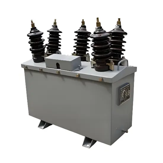
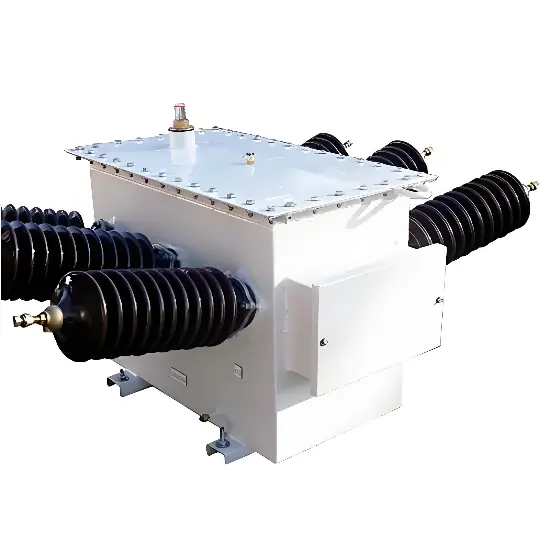
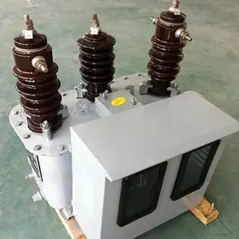
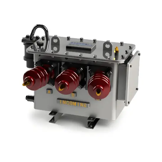
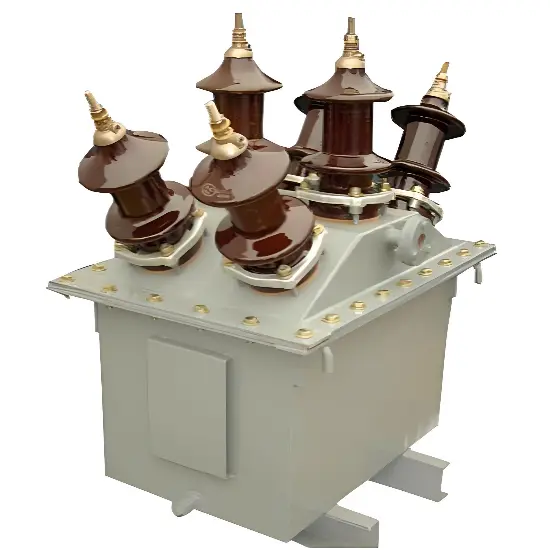
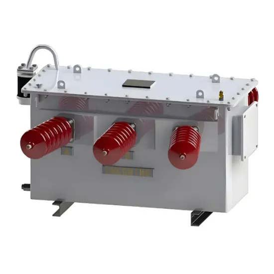
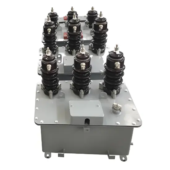
OMU series three phase oil-immersed metering units (hereinafter referred to as metering unit) applies to the rated voltage of 11kV and 33kV,rated frequency of 50-60Hz for power measurement with the three phase three wire and three phase four wire AC network, by the combination of CT/PT together.
Standard
- IEC61869-1.2&3
- Service condition
- Ambient temperature: -40ºC~+85ºC, day temperature difference: 25ºC;
- Altitude:≤3000m area;
- Wind speed no exceeds 35m/s;
- No normally intensity vibration
- No intensity erosion gas, medium place (for example acid, alkali, smother eg.)
- Pollution class: IV class;
- Charge temperature -40ºC~+85ºC.
Note: * Beyond those services condition should enquiry to manufacturer technical dept during order
Product feature
Various irrigation and drainage stations in rural enterprises, township enterprises, processing plants, small and medium factories, mines, transportation, public institutions as well as forestry, energy metering infrastructure temporarily located on site high-voltage transmission lines power station.
The product consists of a combination of transformers and metering meter box composition, combined transformer consists of three voltage transformers and three current transformers are assembled together.
Voltage transformer iron outer core is to use high-quality cold-rolled silicon steel sheet orientation is piled up in the column for the multi-step shape in a column equipped with primary and secondary coils.
Current transformer core is iron formula, with high-quality cold-rolled silicon steel sheet orientation is piled up in the legs of equipped with primary and secondary coils.
Porcelain jacket by conductive bars will lead to a supply voltage, current transformers with wiring. Voltage and current transformers are fixed on the pallet, the pallet support bar by lifting the lid on, and immersed in transformer oil.
High-voltage lead casing, the second casing mounted on the lead cover, tank side with the drain plug grounding bolts.
Technical Specification
|
GENERAL PARTICULARS |
11kV |
33kV |
|
Highest System Voltage( H.S.V.) |
12 KV ( r.m.s.) |
36 KV (r.m.s.) |
|
Power frequency dry/ wet withstand voltage on primary winding for one minute |
28 KV ( r.m.s.) |
70 KV ( r.m.s.) |
|
Lightning Impulse withstand voltage (1.2 x 50 μs |
75 KV ( r.m.s.) |
170 KV ( r.m.s.) |
|
3 Phase 4 Wire with Isolated / Floating neutral as well as solidly earthed |
3 Nos. CTs & 1 No. 3 - Phase PT |
|
|
3 Nos. CTs & 3 Nos. 1 - Phase PT |
||
|
3 Phase 4 Wire with Isolated / Floating neutral as well as solidly earthed. |
2 Nos. CTs & 1 No. 3 - Phase PT |
|
|
2 Nos. CTs & 3 Nos. 1 - Phase PT |
||
|
Short Time Thermal Current (Ith) |
As per customer requirement. |
|
|
In general CT is to be specified with STF of 100 for 1 Sec. or STC (lth) equal to the system fault level whichever is lower. KA ( r.m.s. ) |
||
|
Output |
10 VA to 100 VA for VT |
|
|
5 VA to 30 VA for CT |
||
|
Accuracy Class |
0.2S, 0.2, 0.5S, 0.5, 1.0 for CT. |
|
|
0.2, 0.5 & 1.0 for VT |
||
|
Secondary Current (CT) |
1 Amp or 5 Amp |
|
|
Secondary Voltage (VT) |
110 Ph-Ph or |
|
|
110/v3 V, Ph-Neutral |
||
|
Primary Current (CT) |
As per customer requirement. |
|
|
Primary Voltage (VT) |
11KV, 22KV, 33KV for 3-Phase VT |
|
|
11/v3, 22/v3, 33/v3 for 1-Phase VT |
||
Note: *The above parameter is only subject to our standard design, special requirement can be customized
Voltage transformer (VT’s)
Although less common, where a three phase voltage transformer is supplied it shall meet the requirements of AS1243 – 1982.
For a Three phase Voltage Transformer (VT), Star/star ratios of either:
- (11,000 /√3) / (110 /√3) Volt
- (22,000 /√3) / (110 /√3) Volt
- (33,000 /√3) / (110 /√3) Volt
Rated output: 25 VA per phase
Accuracy Class: 0.5M
Performance: Category B Rated voltage factor 1.1 continuous and 1.5 for 30 seconds.
Current transformer (CT’s)
The current transformers shall meet the requirements of AS 60044.1- 2007. They can be included with the Voltage Transformer as part of a metering unit, or installed in each phase in a high voltage metering chamber.
The following Table provides the preferred ratios and accuracy class for each supply voltage for loads within the specified load range (kVA). Single ratio CTs may also be used where they meet the present and future load of the customer, typically though alternate ratios and specifications must be agreed with the Metering Provider prior to installation.
|
Voltage (Volts) |
CT Ratios (Amps) |
Class & Capacity |
Load Range (kVA) |
|
11,000 |
200 - 100/5 |
0.5 Ext 200% FS10 |
500 - 6000 |
|
22,000 |
100 - 50/5 |
0.5 Ext 200% FS10 |
500 - 6000 |
|
33,000 |
100 – 50/5 |
0.5 Ext 200% FS10 |
500 - 8000 |
The rated output on any CT shall be a minimum of 5 VA on the lowest tap setting. If the load range is outside the above table then the Metering Provider needs to be consulted for the size of the CT’s required. For loads less than 50% of the lowest tap or are intermittent or seasonal in nature (i.e. Wind Generation, Sugar Mills, Cotton Gins etc.) accuracy Class 0.5S CT’s are required to be installed.
The winding and termination
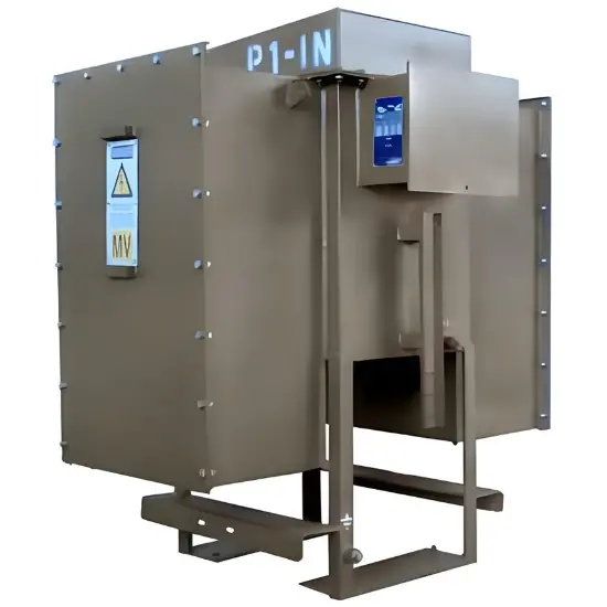
The tails of all instrument transformer secondary windings shall be anchored separately from the windings, so that any stresses applied to the tails does not affect the winding proper. The ends of all available secondary windings shall be brought out into a common sealable waterproof terminal box where this is part of a metering unit.
A common terminal box is preferred but not required where the voltage transformer (i.e. truck type) is located separate from the current transformers. All secondary terminals shall be marked in accordance with the applicable standards.
Should the customer have terminals which need to be accessible in the same terminal box as the metering terminals, then the metering terminals shall be capable of being sealed in their own right (i.e. use of a Perspex cover with sealing screws.).
The terminal box shall be capable of IP54 level of protection if it is going to be located in an outdoor location. The box should be designed so that it is able to breath and condensation doesn’t accumulate.
The voltage secondary terminals shall be fused with 10 Amp HRC sealable fuses.
If the current transformers have multiple tap ratios than all ratios must be available in the marshalling box and accessible to change the CT tap ratio.
Relaterade produkter
-
RMR Utomhus oljebärande kombinerad CT PT-mätningseenhet-11kV 33kV
-
Utomhus markmonterade CT&VT-mätare-6.6kV 11kV 22kV
-
Utomhus bulkmätning enhet tillverkning 15kV 30kV 33kV
-
11kV-33kV oljekylt utomhusenhet kombinerad CTPT/CTVT-enhet
-
Utomhus CT/PT kombinations oljedränkta mätstation 30kV 33kV
-
Trefasoljedoppad utemätarkass 6kV 10kV
-
Utomhus högspänningsmätning låda 6KV 10KV