115kV 123kV 145KV 161kV 170kV Dead Tank SF6 Circuit Breaker Original Manufacturer

| Brand | ROCKWILL |
| Model NO. | 145KV 170kV Dead Tank SF6 Circuit Breaker |
| Rated voltage | 145kV |
| Rated normal current | 1600A |
| Rated frequency | 50/60Hz |
| Rated short circuit breaking current | 25kA |
| Series | RHD |
Description
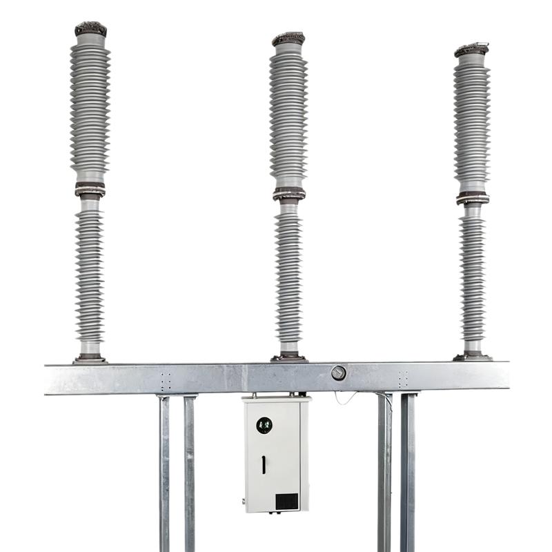
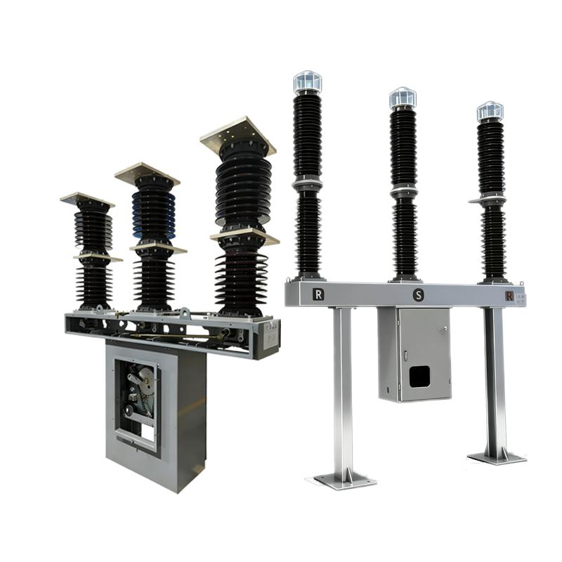
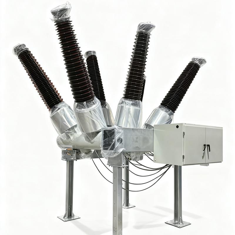
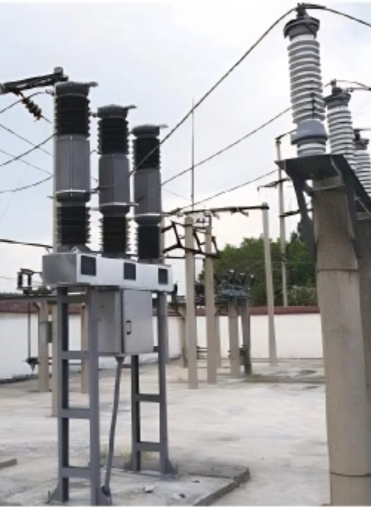
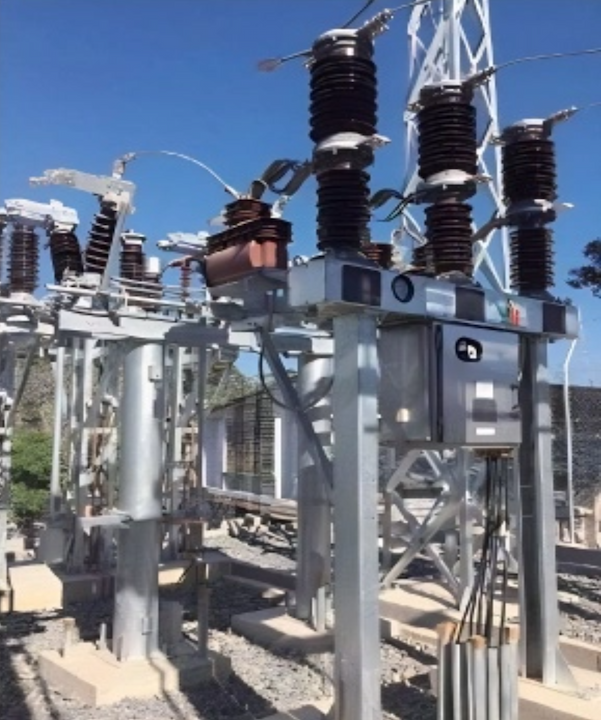
The 115kV 123kV 145KV 161kV 170kV dead tank SF6 circuit breaker is a high-reliability high-voltage device designed to ensure stable operation of power systems. It adopts a dead tank structure, with live parts sealed in a metal casing filled with SF6 gas, ensuring rapid arc extinction and efficient fault current interruption to safeguard grid safety. The low-center-of-gravity design gives it strong seismic resistance, adapting to harsh environments such as extreme climates. The equipment integrates bushings and current transformers to support multi-functional control such as measurement and protection. With long mechanical/electrical life and a sealed structure, maintenance frequency is significantly reduced. Equipped with anti-misoperation interlocking devices, it ensures the safety of personnel and equipment. Widely used in power, metallurgy, transportation and other fields, it performs excellently in medium and high voltage scenarios.
Product Advantages
The spring operating mechanism of the circuit breaker is safe and stable, maintenance-free, and highly reliable, and meets the requirements of oil-free and gas-free operating mechanism.
Self-energy-compressed combined arc extinguisher.
The equipment is shipped after the lightning impact test, which eliminates the hidden danger of insulation discharge caused by production and assembly, and ensures the stable and reliable product quality.
The quality of the insulators is stable and reliable.
High parameterization: The technical parameters of the products are all of the highest standards in the industry.
The domestic first-class design team, suppliers and internal control system ensure the safety, stability and reliability of the products, and the products and inspection standards manufactured in the factory have been recognized by the State Grid and the Southern Power Grid Supervision.
Using advanced R&D tools such as finite element analysis software, functional analysis, whole-process quality characteristic chain, size chain analysis, potential failure mode and effect analysis (FEMA), etc., the modular design is realized on the basis of ensuring the safety, stability and reliability of product performance.
Earthquake resistance of magnitude 9.
Product features:
Spring operating mechanism, reliable performance;
Excellent breaking performance
E2-M2-C2 circuit breaker, electrical life 20 times, mechanical life 10000 times.
Strong rated flow capacity;
Excellent insulation level, small local discharge;
Excellent corrosion resistance;
Advanced design tools;
Strict process assembly and quality control.
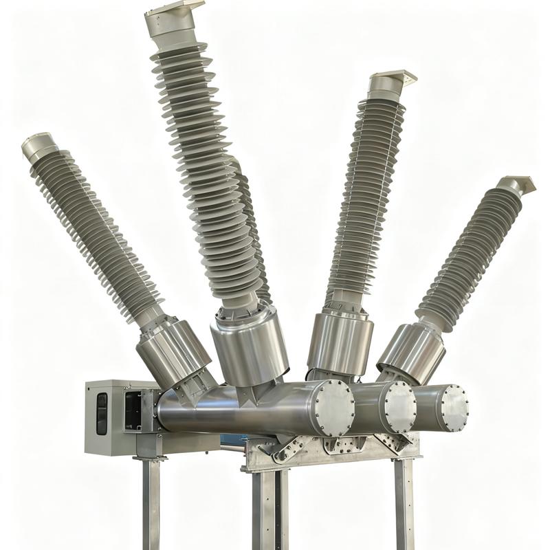
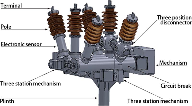
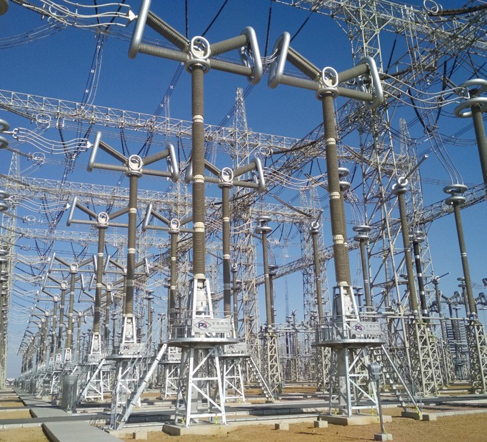
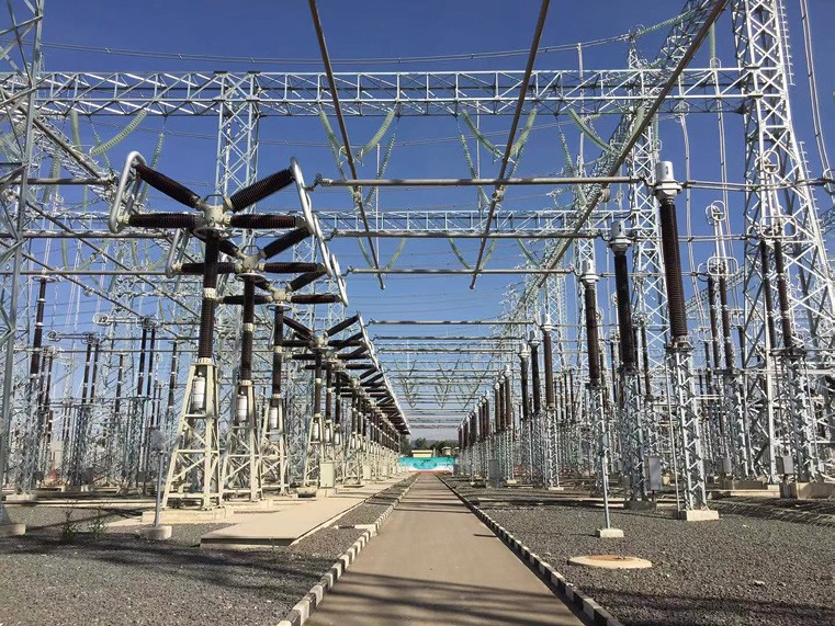
System Architecture
The gas-insulated metal composite combined electrical appliance (HGIS) is composed of several standard functional modules, such as circuit breaker GCB (single and double busbars), isolation-grounding switch TPS, voltage transformer PT, current transformer CT, etc. These modules have the same interface form and size. Various modules can be combined to meet the design and layout requirements of various substations.
Single-busbar single-isolation scheme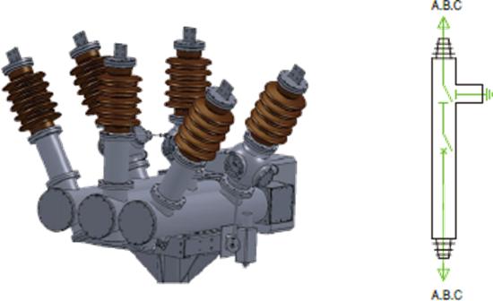
Single-busbar double -isolation scheme
Main characteristics
Electrical
| Item | Unit | Parameters | |||
| Rated maximum voltage | kV | 115kV 123kV 145KV 161kV 170kV | |||
| Rated maximum current | A | 1600/2500/3150/4000 | |||
| Rated frequency | Hz | 50/60 | |||
| 1min Power frequency withstand voltage | kV | 230 | |||
| Lightning impulse withstand voltage | kV | 550 | |||
| First open pole factor | 1.5/1.5/1.3 | ||||
| Rated short circuit breaking current | kA | 25/31.5/40 | |||
| Rated short - circuit duration | s | 4/3 | |||
| Rated out - of - phase breaking current | 10 | ||||
| Rated cable charging current | 10/50/125 | ||||
| Rated peak value withstand current | kA | 80/100/125 | |||
| Rated making current (peak) | kA | 80/100/125 | |||
| Creepage distance | mm/kV | 25 - 31 | |||
| SF6 gas leakage rate (per year) | ≤1% | ||||
| Rated SF6 gas pressure(20℃ gauge pressure) | Mpa | 0.5 | |||
| Alarm/blocking pressure(20℃ gauge pressure) | Mpa | 0.45 | |||
| SF6 annual gas leakage rate | ≤0.5 | ||||
| Gas moisture content | Ppm(v) | ≤150 | |||
| Heater voltage | AC220/DC220 | ||||
| Voltage of control circuit | DC | DC110/DC220/DC230 | |||
| Voltage of energy - store motor | V | DC 220/DC 110/AC 220/DC230 | |||
| Applied standards | GB/T 1984/IEC 62271 - 100 | ||||
Mechanical
| Name | unit | Parameters | |||
| Opening time | ms | 27±3 | |||
| Closing time | ms | 90±9 | |||
| Minute and conjunction time | ms | 300 | |||
| Together--ivide the time | ms | ≤60 | |||
| Simultaneity of opening | ms | ≤3 | |||
| Closing simultaneity | ms | ≤5 | |||
| Moving contact stroke | mm | 150+2-4 | |||
| Contact contact stroke | mm | 27±4 | |||
| Opening speed | m/s | 4.5±0.5 | |||
| Closing speed | m/s | 2.5±0.4 | |||
| Mechanical life | times | 6000 | |||
| Operation sequence | O - 0.3s - CO - 180s - CO | ||||
| Note: The opening and closing speed and time are the characteristic values of the circuitbreaker when it is single divided and closed under rated conditions. The closing speed is theaverage speed of the moving contact from the rigid closing point to 10 ms before closing, andthe opening speed is the average speed of the moving contact within 10 ms from the justequinox to 10 ms after the separation. | |||||
Use of the environment
Installation location: indoor/outdoor;
Ambient air temperature :
Maximum temperature: +55℃
Minimum temperature: -40℃; Maximum daily temperature difference: 32 K;
Altitude: ≦3000m;
Sunshine intensity (noon on sunny day): 1000 W/㎡;
Pollution level: III./IV. grade;
Icing thickness: 10mm/20mm;
Wind speed/wind pressure: 34m/s (equivalent to 700Pa on the surface of the cylinder);
Humidity: average daily relative humidity: ≦95%; Monthly average relative humidity: ≦90%;
Earthquake resistance: nine degrees;
Horizontal acceleration: 0.3g;
Vertical acceleration: 0.15g.
Use of the product
In densely populated areas, in harmony with existing buildings, in important and critical substations, in confined space substation expansions, in flexible retrofits and replacements, in places with heavy loads, for economical and reliable energy management, in power stations, etc.

1. Select the circuit breaker corresponding to the voltage level based on the power grid level
The standard voltage (12/24/40.5/72.5/126/170/245/363/420/550/800/1100kV) is matched with the corresponding nominal voltage of the power grid. For example, for a 35kV power grid, a 40.5kV circuit breaker is selected. According to standards such as GB/T 1984/IEC 62271-100, the rated voltage is ensured to be ≥ the maximum operating voltage of the power grid.
2. Applicable scenarios for non-standard customized voltage
Non standard customized voltage (11/22/44/52/132/230/275/300/345/400/380/765kV) is used for special power grids, such as the renovation of old power grids and specific industrial power scenarios. Due to the lack of suitable standard voltage, manufacturers need to customize according to power grid parameters, and after customization, insulation and arc extinguishing performance must be verified.
3. The consequences of selecting the wrong voltage level
Choosing a low voltage level can cause insulation breakdown, leading to SF leakage and equipment damage; Choosing a high voltage level significantly increases costs, increases operational difficulties, and may also result in performance mismatch issues.
Related Products
-
HECS Series Generator Circuit-breakers

-
40.5kV HV Vacuum SF6 circuit breaker
-
550kV Dead tank SF6 circuit breaker

-
40.5kV HV SF6 circuit breaker
-
1100kV UHV SF6 Circuit Breaker
-
550kV HV SF6 Circuit Breaker
-
252kV 363 kV HV SF6 Circuit Breaker
-
252kV outdoor self-energy power high voltage SF6 circuit breaker
-
72.5kV HV SF6 circuit breaker

-
126kV 145kV high voltage SF6 circuit breaker