| Brand | ROCKWILL |
| Model NO. | Customization of Dead tank SF6 Gas Circuit-Breaker |
| Rated voltage | 220kV |
| Rated normal current | 3150A |
| Rated frequency | 50/60Hz |
| Series | RHD |
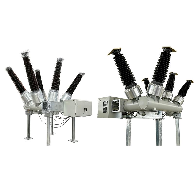
Product Overview
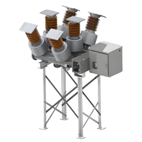
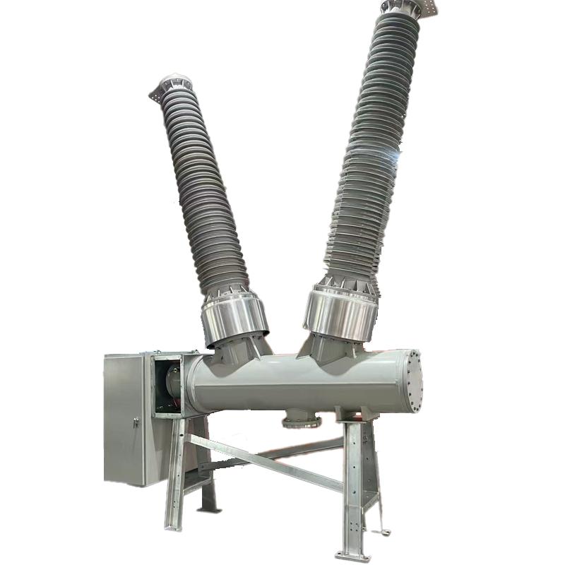
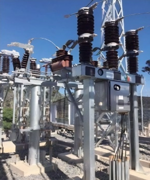
The RHD Series Dead-Tank SF6 Circuit Breaker is engineered for 'customized high-voltage power system solutions', covering standard voltage grades from RHD-40.5 to RHD-550 and supporting 'non-standard voltage customization' to precisely match your unique grid upgrade or construction needs. As a dead-tank type, its grounded tank isolates high-voltage components, ensuring superior insulation performance and safety—making it the go-to choose for demanding high-voltage scenarios.
About customization
We offer full customization services for voltage classes, including single-phase, two-phase, and three-phase configurations, as well as non-standard voltage/current solutions. Examples of available voltage and current specifications include 1250 A 75 kV, 3200 A 46 kV, 60 kV, 69 kV, and 75 kV (we support customization ranging from 10 kV to 800 kV for voltage and 1250 A to 6300 A for current). Regardless of your power grid's voltage specifications, we tailor the circuit breaker for seamless integration.
All products are fully assembled and tested at our factory before being shipped directly to your site—no disassembly of key components is required. This eliminates the need for on-site high-voltage testing, significantly saving you time and costs.
Key features
1. Superior Seismic Resistance
Adopting a low-center-of-gravity design, the breaker can withstand an earthquake intensity of up to 9 degrees, ensuring stable performance in seismic-prone areas—consistent with the RHD series’ proven anti-seismic capability.
2. Excellent Arc-Extinguishing Performance & Long Service Life
Leveraging the high arc-extinguishing efficiency of SF6 gas, the breaker achieves a rated short-circuit breaking current of ≥50kA. It boasts an electrical life of more than 20 operations and a mechanical life of up to 10,000 cycles, significantly reducing equipment replacement and maintenance costs.
3. Low SF6 Gas Leakage Rate
The hermetic metal tank structure minimizes SF6 gas leakage, with an annual leakage rate of ≤1%—far below industry averages. This design not only avoids safety hazards from gas leakage but also reduces environmental impact.
4. Modular Design & Flexible Expansion
It supports on-demand configuration of built-in current transformers (CTs), with up to 15 CTs available for measurement or protection purposes. The standardized module interface allows flexible combination to meet diverse substation design and layout requirements, especially suitable for space-constrained scenarios.
5. Strong Environmental Adaptability
The breaker operates stably in extreme conditions: ambient temperature ranging from -40℃ to +55℃, maximum daily temperature difference of 32K, altitude up to 3,000m, and air pollution level up to Class IV. It also resists wind pressure of 700Pa (equivalent to 34m/s wind speed) and icing thickness of up to 20mm.
6. Comprehensive Safety Protection
Equipped with anti-mis operation interlocking devices, it effectively prevents accidents caused by incorrect operations. Before delivery, the breaker undergoes lightning impulse tests to eliminate insulation discharge risks from production and assembly, ensuring reliable quality.
7. Maintenance-Free Operating Mechanism
It adopts a spring-operated mechanism that is oil-free, gas-free, and maintenance-free. This mechanism delivers stable performance, low noise, and high reliability, reducing long-term operational workload.
Technology Parameters
| Item | Unit | Parameters | |||
| customization of Rated Voltage | kV | 11kV/12kV/13.8kV/15kV/22kV/33kV/44kV/60kV/63kV/66kV/69kV/88kV/115kV/123kV/125kV/126kV/132kV/138kV/145kV/150kV/170kV/220kV/225kV/230kV/245kV/275kV/330kV/345kV/400kV/765kV/800kV |
|||
| customization of Rated current | A | 1250 to 6300 | |||
| Rated frequency | Hz | 50/60 | |||
| 1min Power frequency withstand voltage | kV | Max to 750 | |||
| Lightning impulse withstand voltage | kV | Max to 1675 | |||
| First open pole factor | 1.5/1.3/1.55 | ||||
| Rated short circuit breaking current | kA | 16 to 63 | |||
| Rated short - circuit duration | s | 4,3 | |||
| Rated out - of - phase breaking current | 10 | ||||
| Rated cable charging current | 10/50/125 | ||||
| Rated peak value withstand current | kA | 80/100/125 | |||
| Rated making current (peak) | kA | 80/100/125 | |||
| Creepage distance | mm/kV | 25 - 31 | |||
| SF6 gas leakage rate (per year) | ≤1% | ||||
| Rated SF6 gas pressure(20℃ gauge pressure) | Mpa | 0.5/0.4,0.5,0.6 | |||
| Alarm/blocking pressure(20℃ gauge pressure) | Mpa | 0.45/0.4,0.35/0.33,0.45/0.40,0.55/0.50 | |||
| SF6 annual gas leakage rate | ≤0.5 | ||||
| Gas moisture content | Ppm(v) | ≤150 | |||
| Heater voltage | AC220/DC220 | ||||
| Voltage of control circuit | DC | DC110/DC220/DC230 | |||
| Voltage of energy - store motor | V | DC 220/DC 110/AC 220/DC230 | |||
| Applied standards | GB/T 1984/IEC 62271 - 100 | ||||
| Name | unit | Parameters | |||
| Opening time | ms | 27±3 | |||
| Closing time | ms | 90±9 | |||
| Minute and conjunction time | ms | 300 | |||
| Together--ivide the time | ms | ≤60 | |||
| Simultaneity of opening | ms | ≤3 | |||
| Closing simultaneity | ms | ≤5 | |||
| Moving contact stroke | mm | 150+2-4 | |||
| Contact contact stroke | mm | 27±4 | |||
| Opening speed | m/s | 4.5±0.5 | |||
| Closing speed | m/s | 2.5±0.4 | |||
| Mechanical life | times | 6000 | |||
| Operation sequence | O - 0.3s - CO - 180s - CO | ||||
| Note: The opening and closing speed and time are the characteristic values of the circuitbreaker when it is single divided and closed under rated conditions. The closing speed is theaverage speed of the moving contact from the rigid closing point to 10 ms before closing, andthe opening speed is the average speed of the moving contact within 10 ms from the justequinox to 10 ms after the separation. | |||||
Application Scenarios
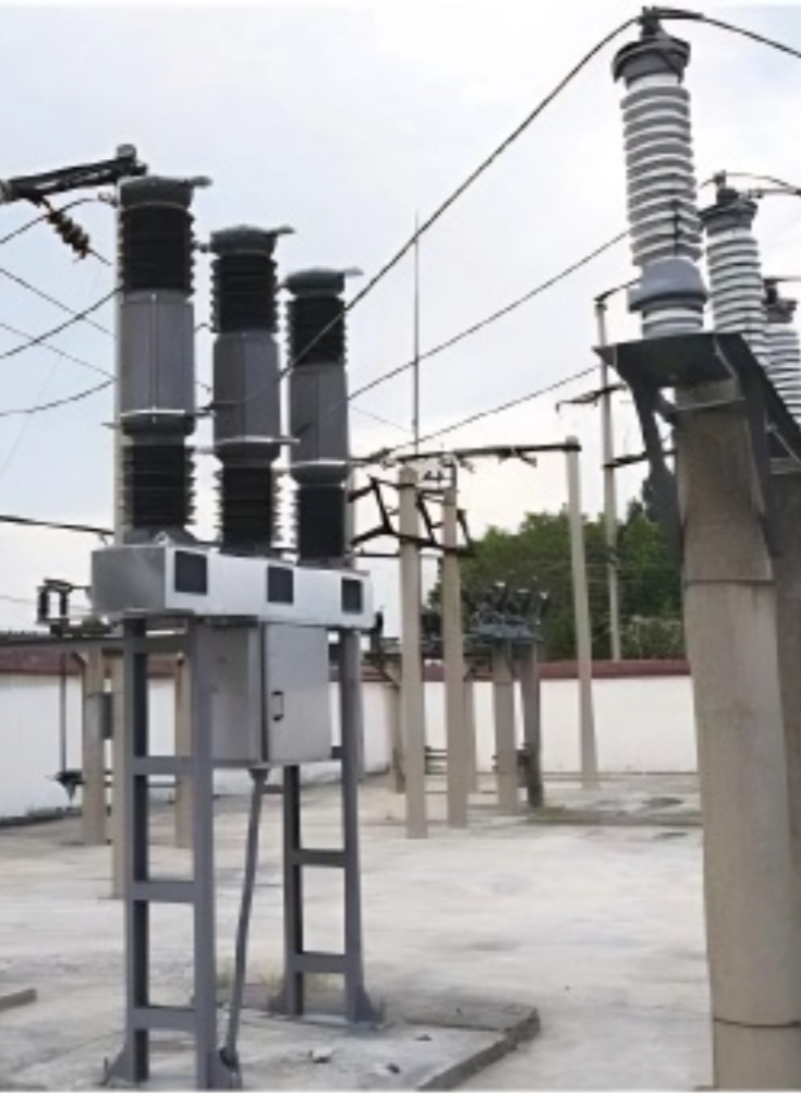
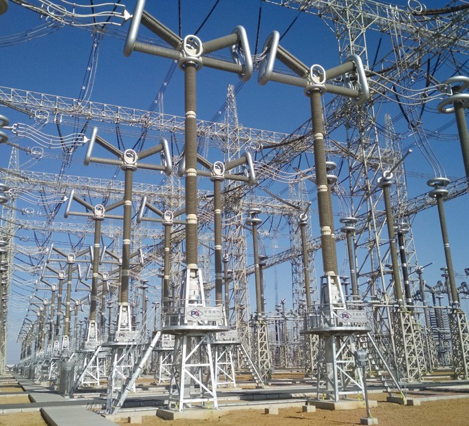
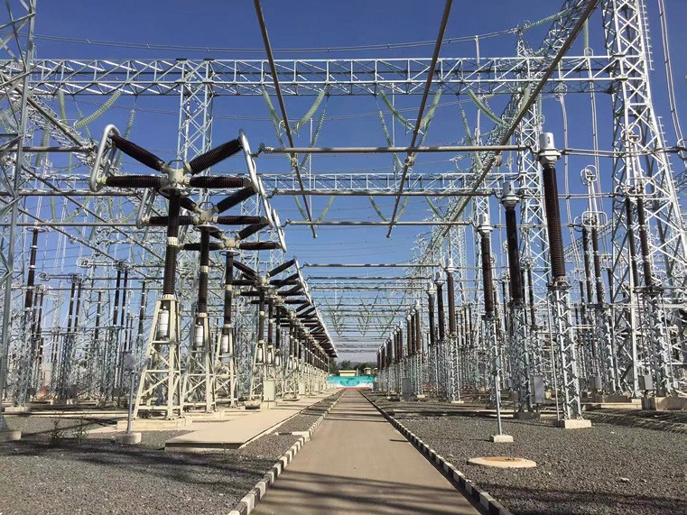
Large Hub Substations
Ideal for 220kV+ key hub substations, the customized RHD breaker controls and protects main power circuits. Its non-standard voltage adaptability ensures seamless integration into existing or upgraded grid architecture.
New Energy Grid-Connection Systems
Suitable for high-voltage grid connections in wind and solar power bases. Custom voltage ratings ensure reliable integration of renewable energy into the main grid, even in projects with unique voltage requirements.
Industrial High-Voltage Power Systems
Perfect for heavy industries (metallurgy, chemicals) with specialized voltage needs. The breaker’s robust performance and customizability guarantee stable power supply for high-power industrial equipment.
1. Select the circuit breaker corresponding to the voltage level based on the power grid level
The standard voltage (12/24/40.5/72.5/126/170/245/363/420/550/800/1100kV) is matched with the corresponding nominal voltage of the power grid. For example, for a 35kV power grid, a 40.5kV circuit breaker is selected. According to standards such as GB/T 1984/IEC 62271-100, the rated voltage is ensured to be ≥ the maximum operating voltage of the power grid.
2. Applicable scenarios for non-standard customized voltage
Non standard customized voltage (11/22/44/52/132/230/275/300/345/400/380/765kV) is used for special power grids, such as the renovation of old power grids and specific industrial power scenarios. Due to the lack of suitable standard voltage, manufacturers need to customize according to power grid parameters, and after customization, insulation and arc extinguishing performance must be verified.
3. The consequences of selecting the wrong voltage level
Choosing a low voltage level can cause insulation breakdown, leading to SF leakage and equipment damage; Choosing a high voltage level significantly increases costs, increases operational difficulties, and may also result in performance mismatch issues.
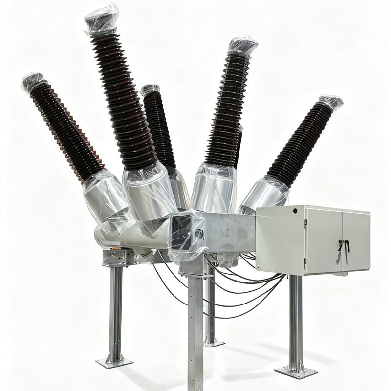
Integral Tank Structure:
-
Integral Tank Structure: The breaker's arc quenching chamber, insulating medium, and related components are sealed within a metal tank filled with an insulating gas (such as sulfur hexafluoride) or insulating oil. This forms a relatively independent and sealed space, effectively preventing external environmental factors from affecting the internal components. This design enhances the insulation performance and reliability of the equipment, making it suitable for various harsh outdoor environments.
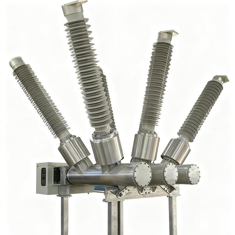
Arc Quenching Chamber Layout:
-
Arc Quenching Chamber Layout: The arc quenching chamber is typically installed inside the tank. Its structure is designed to be compact, enabling efficient arc quenching within a limited space. Depending on different arc quenching principles and technologies, the specific construction of the arc quenching chamber may vary, but generally includes key components such as contacts, nozzles, and insulating materials. These components work together to ensure that the arc is quickly and effectively extinguished when the breaker interrupts the current.
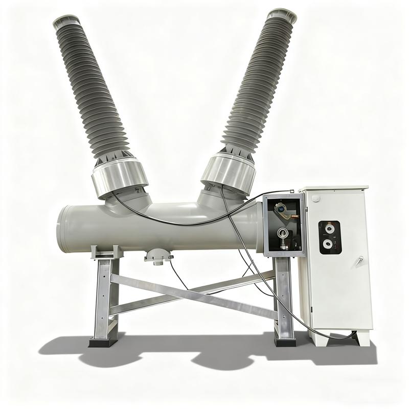
Operating Mechanism:
-
Operating Mechanism: Common operating mechanisms include spring-operated mechanisms and hydraulic-operated mechanisms.
-
Spring-Operated Mechanism: This type of mechanism is simple in structure, highly reliable, and easy to maintain. It drives the opening and closing operations of the breaker through the energy storage and release of springs.
-
Hydraulic-Operated Mechanism: This mechanism offers advantages such as high output power and smooth operation, making it suitable for high-voltage and high-current class breakers.
-
40.5kV HV Vacuum SF6 circuit breaker
-
126kV High-voltage AC Dead tank SF6 circuit breaker

-
40.5kV Dead tank SF6 circuit breaker

-
363 kV Dead tank SF6 circuit breaker

-
252kV Outdoor Dead Tank SF6 Circuit Breaker
-
550kV Dead tank SF6 circuit breaker

-
420kV Dead tank SF6 circuit breaker
-
40.5kV HV SF6 circuit breaker
-
1100kV UHV SF6 Circuit Breaker
-
550kV HV SF6 Circuit Breaker
-
 Design Solution of 24kV Dry Air Insulated Ring Main UnitThe combination of Solid Insulation Assist + Dry Air Insulation represents the development direction for 24kV RMUs. By balancing insulation requirements with compactness and employing solid auxiliary insulation, insulation tests can be passed without significantly increasing phase-to-phase and phase-to-ground dimensions. Encapsulating the pole column solidifies the insulation for the vacuum interrupter and its connecting conductors.Maintaining the 24kV outgoing busbar phase spacing at 110mm,Rockwill16/08-2025
 -
 Optimization Design Scheme for the 12kV Air-Insulated Ring Main Unit Isolating Gap to Reduce Breakdown Discharge ProbabilityWith the rapid development of the power industry, the ecological concept of low-carbon, energy-saving, and environmental protection has been deeply integrated into the design and manufacturing of power supply and distribution electrical products. The Ring Main Unit (RMU) is a key electrical device in distribution networks. Safety, environmental protection, operational reliability, energy efficiency, and economy are inevitable trends in its development. Traditional RMUs are primarily representedRockwill16/08-2025
 -
 Analysis of Common Problems in 10kV Gas-Insulated Ring Main Units (RMUs)Introduction:10kV gas-insulated RMUs are widely used due to their numerous advantages, such as being fully enclosed, possessing high insulation performance, requiring no maintenance, having a compact size, and offering flexible and convenient installation. At this stage, they have gradually become a critical node in urban distribution network ring-main power supply and play a significant role in the power distribution system. Problems within gas-insulated RMUs can severely impact the entire diRockwill16/08-2025
 -
 SF6-Free Solution for Air-Insulated/Eco-friendly Gas Ring Main UnitsⅠ. Technical Bottlenecks of SF₆ SubstitutionInsulation Medium Performance Gapo Dried Air/N₂ insulation strength is only 1/3 of SF₆, requiring expansion of contact gap from 60mm to ≥150mm.o Conventional spring mechanisms lack energy to drive rapid closure of large gaps, easily causing contact ablation due to pre-strike.o Synthetic gases (e.g., C4+CO₂) decompose under arcing, leading to irreversible insulation degradation.Mechanical Structural Limitationso National Grid standardization fixRockwill16/08-2025
 -
 Implementation Scheme for Installing Lightning Arresters or Voltage Transformers in Gas-Insulated Ring Main UnitsAccording to insulation type, ring main units (RMUs) can be categorized as gas-insulated or air-insulated. The former installs primary circuit components in a sealed metal enclosure filled with low-pressure gas (primarily SF₆ or mixed gases) as the insulating medium, using cable terminals for incoming and outgoing lines. Due to superior insulation, compact size, and modular design, they are widely used in 10kV outdoor distribution substations and prefabricated transformer stations. However, theiRockwill16/08-2025
 -
 Pressure Relief Safety Solution for Gas-Insulated Ring Main UnitsⅠ. Problem ContextAs a core component in urban power distribution networks, ring main units (RMUs) are widely used in residential areas, factories, and public buildings due to their compact structure, low cost, and high reliability. However, internal equipment failures or arc faults may generate high-temperature, high-pressure gas, leading to cabinet explosions that endanger personnel and equipment. While traditional sealed designs maintain insulation integrity, they fail to rapidly release sudRockwill16/08-2025