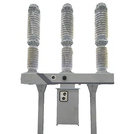
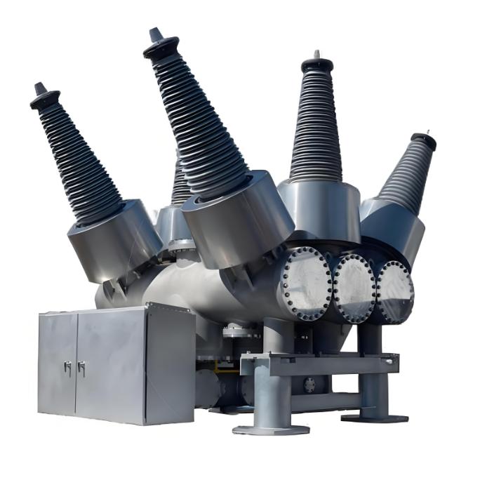
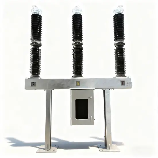
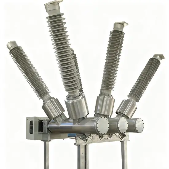
120kV 168kV 204 kV Tank Type Vakuumbrytare (VCB)
| Varumärke | ROCKWILL |
| Modellnummer | 120kV 168kV 204 kV Tank Type Vacuum Circuit Breaker(VCB) |
| Nominell spänning | 204kV |
| Nominell ström | 2000A |
| Nominell frekvens | 50/60Hz |
| Serier | VBO |
Beskrivning
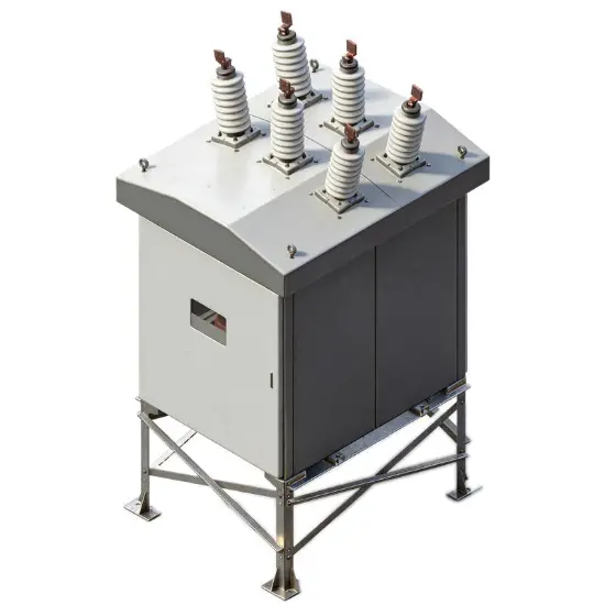
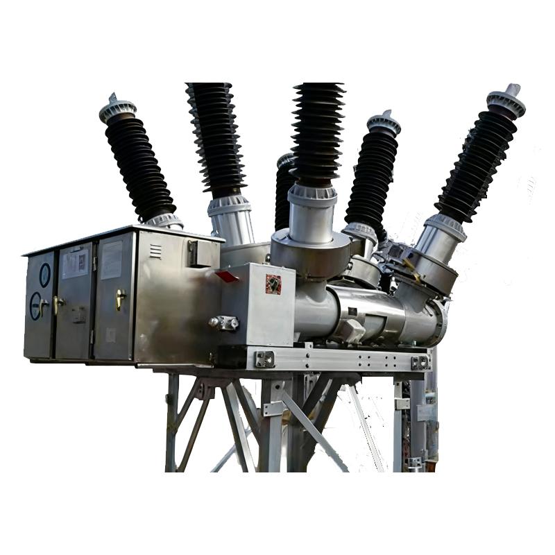
120kV, 168kV och 204kV tanktypens vakuumbrytare (VCBs) är högspänningsströmsväxlingslösningar utformade för robust prestanda i medelspänningsnät för överföring och distribution. De är utformade med en sluten tankstruktur (tanktyp) för att omsluta kärnkomponenter, vilka använder vakuumavbrottare för tillförlitlig bågutsläckning, vilket säkerställer säker och effektiv strömavbrottning i medel- till högspänningsystem.
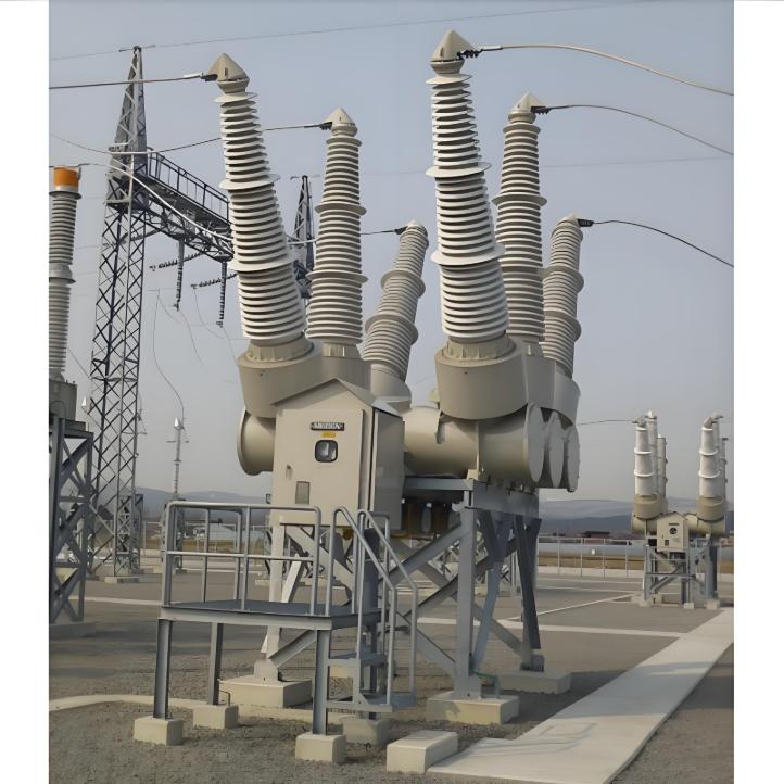
De är idealiska för nätverksstationer, industriella elnät och integrationsprojekt för förnybar energi (som vind- och solcellspark), de täcker en mångsidig spänningsspanning för att möta olika nätverkskrav. Deras tanktypsdesign förbättrar isoleringens stabilitить и устойчивость к окружающей среде, в то время как технология вакуума исключает необходимость использования парниковых газов, таких как SF₆, что соответствует глобальным инициативам по снижению углеродного следа. Будь то при размещении в суровых условиях на открытом воздухе или в компактных внутренних подстанциях, они обеспечивают стабильную работу, длительный срок службы и сокращение затрат на протяжении всего жизненного цикла, делая их устойчивым выбором для современной энергетической инфраструктуры.
Produktfunktioner
Miljövänlig och utmärkt motståndskraft mot jordskalv. Eftersom en vakuumavbrottsdel (VI) används i avbrottsdelen har den utmärkt avbrottsprestanda och det uppstår ingen gasdekomposition vid strömavbrott. En buschingsströmförstärkare (BCT) kan inbyggas i tanken. Detta minskar fotavtrycket. Det krävs inte inspektion av avbrottsdelen genom öppning. Det kan realisera besparing på underhållskostnader. Det minskar också det nödvändiga mängden SF6-gas till ungefär 1/3 jämfört med gasbrytaren (GCB).
Utmärkt avbrottsprestanda genom vakuumisolering av avbrottsdelen
Mindre fotavtryck genom användning av inbyggd buschings CT (BCT)
Det kan spara underhållskostnader eftersom det inte krävs inspektion av avbrottsdelen genom öppning.
Det kan realisera kostnadsreduktion för livscykel (LCC) med ca 40% jämfört med GCB
Utmärkt motståndskraft mot jordskalv tack vare låg tyngdpunkt
Miljövänlig typ. Den kan minska mängden SF6-gas jämfört med GCB
Specifikationer
Nominell spänning (kV) |
120kV |
168kV |
204kV |
|||
Nominell ström (A) |
1200 |
2000 |
1200 |
2000 |
1200 |
2000 |
Nominell avbrytande ström (kA) |
31.5 |
31.5 |
40 |
31.5 |
40 |
|
Nominell öppningstid (s) |
0.06 (5 cykler) |
0.037 |
||||
Nominell avbrottscykel (cykler) |
5/3 |
3 |
||||
Driftsläge |
A (O - 1 min - CO - 3 min - CO), B (CO - 15 sek - CO), R (O - 0.35 sek - CO - 1 min - CO) |
|||||
Stängningstid (s) |
0.13 |
|||||
Nominell stängningsbetjäningsspänning (V) |
DC100 |
|||||
Nominell motorstyrspänning (V) |
DC100 |
|||||
Isoleringmedium |
SF6-gas |
|||||
Nominell gastryck (MPa-g) |
0.15 (20℃) |
|||||
Betjänningssystem |
Motorladdad fjäder |
|||||
Tillämpliga standarder |
JEC-2300 (1998) |
|||||
Det läckage av SF₆-gas måste hållas på ett extremt lågt nivå, vanligtvis inte överstigande 1 % per år. SF₆-gas är en kraftfull växthusgas, med en växthuseffekt som är 23 900 gånger större än koldioxid. Om en läcka uppstår kan det inte bara orsaka miljöförorening utan också leda till en minskning av gastrycket i bågutsläckningskammaren, vilket påverkar strömavbrytarens prestanda och tillförlitlighet.
För att övervaka läckage av SF₆-gas installeras vanligtvis gasläckagedetekteringsenheter på tankströmavbrytare. Dessa enheter hjälper till att snabbt identifiera eventuella läckor så att lämpliga åtgärder kan vidtas för att hantera problemet.
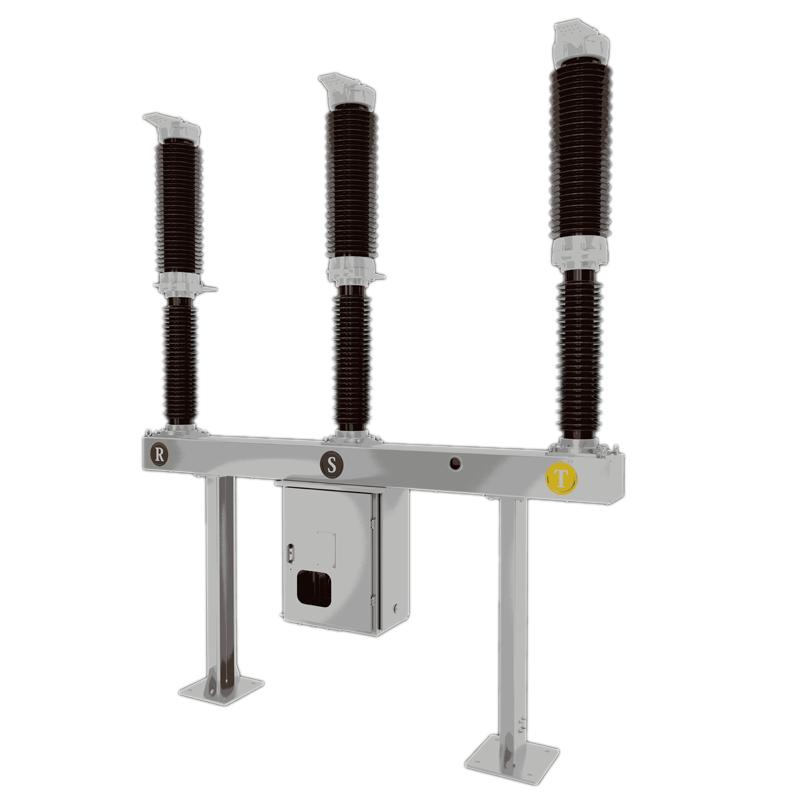
Integrerad tankstruktur:
-
Integrerad tankstruktur: Böjarens bågläckningskammare, isolerande medium och relaterade komponenter är seglade inuti en metalltank fylld med ett isolerande gas (som hexafluorid) eller isolerande olja. Detta bildar en relativt oberoende och seglad yta, vilket effektivt förhindrar att externa miljöfaktorer påverkar de interna komponenterna. Denna design förbättrar utrustningens isoleringsprestanda och tillförlitlighet, vilket gör den lämplig för olika hårda utomhusmiljöer.
Layout av bågläckningskammare:
-
Layout av bågläckningskammare: Bågläckningskammaren installeras vanligtvis inuti tanken. Dess struktur är utformad för att vara kompakt, vilket möjliggör effektiv bågläckning inom begränsat utrymme. Beroende på olika bågläckningsprinciper och teknologier kan den specifika konstruktionen av bågläckningskammaren variera, men den innehåller generellt viktiga komponenter som kontakter, munstycken och isolerande material. Dessa komponenter samarbetar för att säkerställa att bågen snabbt och effektivt släcks när böjaren avbryter strömmen.
Drivmekanism:
-
Drivmekanism: Vanliga drivmekanismer inkluderar fjäderdrivna mekanismer och hydrauliska drivmekanismer.
-
Fjäderdriven mekanism: Denna typ av mekanism har en enkel struktur, är mycket tillförlitlig och lättenlig. Den drivs av energilagring och -frigörelse i fjädern, vilket styr öppnings- och stängningsoperationerna av böjaren.
-
Hydraulisk mekanism: Denna mekanism erbjuder fördelar som hög utmatningskraft och jämn drift, vilket gör den lämplig för högspännings- och högströmsklassens böjare.
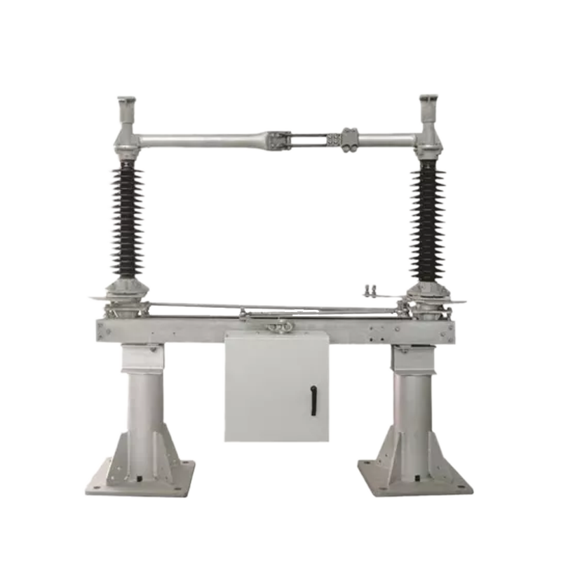
Relaterade produkter
-
72,5kV högspänningsvakuummbrytare
-
40,5kV 72,5kV 145kV 170kV 245kV Död tank Vakuumbrytare

-
52kV 72,5kV 123kV 145kV 170kV 252kV 363kV Livtank Vakuumbrytare

-
126(145)kV högspänningsvakuumssäkring
-
SDF-serien horisontell centrumavbrottsdisjunktor
-
145kV torr Luftisolerad Död Tank Vakuumbrytare
-
Anpassning 145kV/138kV/230kV eller annan livtank-vakuumbrytare
-
Anpassning 145kV/138kV/230kV eller annan död tank vakuum brytare
-
MV utomhus vakuumkretsutslagare för anläggning